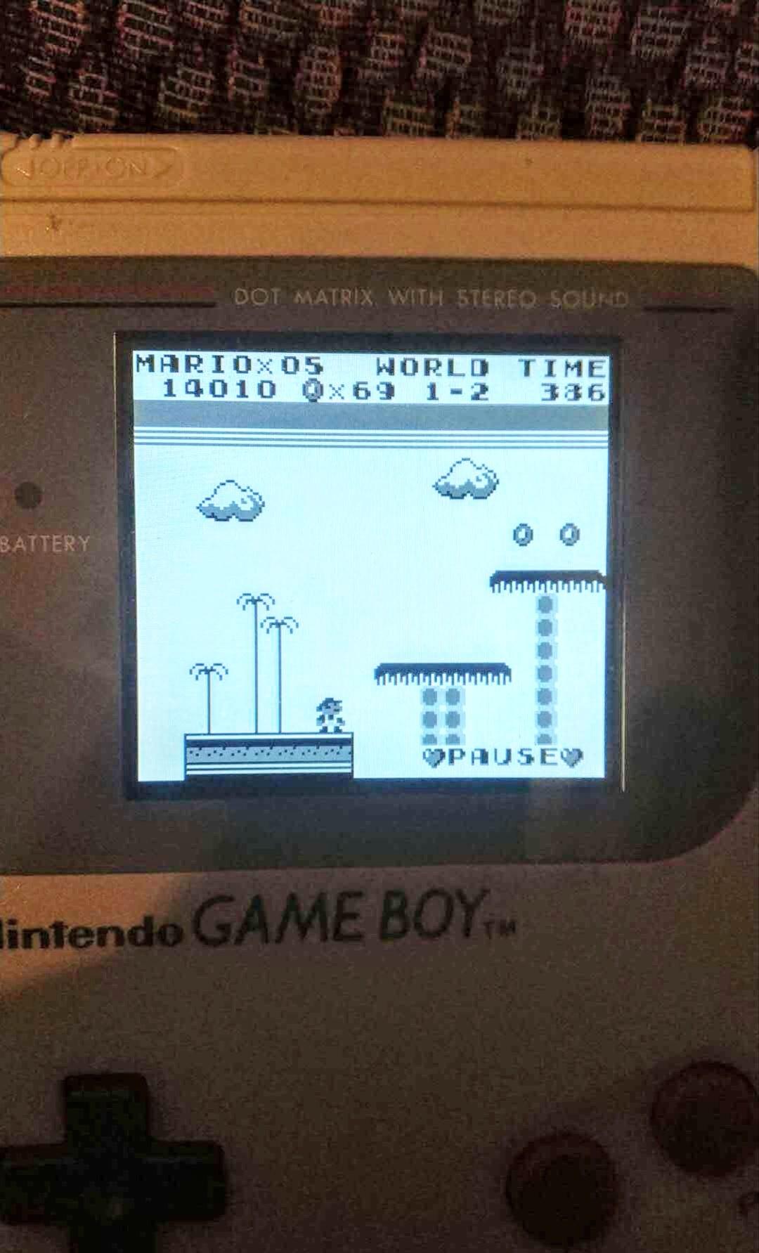
The thin ribbon cables used to drive the LCD were actually sandwiched inside the panes of glass that constitute the LCD. The most likely cause of the issue is what Andrew said. įrom there, there's not a lot of places to go. There are some decent Game Boy schematics on dev'rs if you need. If you identify any bad components, solder in a replacement and see if that works. burnt transistors, charred board, leaky/dry electrolytic caps. I would also check all components on the PCBs for signs of damage, e.g. If it isn't, replace it and see if that solves the issue. Using B/W color scheme.Ĭurrently working on getting the SN74LVC8T245PWR level shifters working and I will be able to pull live data from the Gameboy LCD data bus.I would check to see if the pot that controls the contrast is functional with a multimeter. Gameboy DMG-01 screenshot displayed from DE0 FPGA RAM. Simulating original Gameboy “yellow-green” pallet. mif format (memory initialization file) convertor to display some Gameboy screenshots on the VGA Monitor.
#Gameboy dmg video code#
Then using my DE0_VGA_Driver I started writing the code take data from RAM on the FPGA and output it on the VGA monitor. Frame zoomed in a bit to see the individual horizontal lines. I had the trigger set to wait for the V-Sync signal.

Open Bench Logic Sniffer connected to Gameboy DMG-01.Ĭonnected up the Open Bench Logic Sniffer and powered up the Gameboy with a game in it then ran the capture. V-Sync should be 60Hz, Pixel Clock 4Mhz, and H-Sync 9.2kHz. The connector between the front and back of the Gameboy is where I will tap into the signals to sneak a peak. Front board and LCD connector for the Gameboy DMG-01. Kidna like philips heads but with 3 “wings” instead of 4. Needed some cleaning but it worked and had the battery cover! Taking apart the Gameboy DMG-01. Purchased a Gameboy DMG-01 off eBay for $20. I am using a SN74LVC8T245PWR 8-bit directional level shifter to do the translation on the IO wing board. The Gameboy is a 5V device and the DE0 does not have 5V tolerant IO.

I will use the IO wing to level shift the signals from the Gameboy’s LCD screen so my DE0 can capture the data. This is the project that the DE0 Digital IO Wing is for. I would like to move it to a newer platform like a 10M08SCU169C8G. The FPGA is an older Cyclone 4 module (EP4CE6E22C8N) but it should do the trick and is still fairly affordable. To quicken the development process I am going to lift the FPGA design block from the ChromaColor project. First order of business is to start making some dedicated hardware for the Gameboy.

With that out of the way… Current plan is to just look at my past incomplete projects and either finish them or kill them off. I will be putting more effort into posting here. Typically they just go to my twitter account and I talk about them on the podcast. I have been doing side projects for fun but I have just been very bad about posting them here. It is a weekly electronics podcast and we are currently on episode 119…and we have not missed a single week! I also am the co-host of the MEP or MacroFab Engineering Podcast. It is the company I co-founded a bit over 4 years ago now. Instead of trying to have an excuse of why I have not been posting here.


 0 kommentar(er)
